 |
| September 10, 2013 | Volume 09 Issue 34 |
Designfax weekly eMagazine

Archives
Partners
Manufacturing Center
Product Spotlight
Modern Applications News
Metalworking Ideas For
Today's Job Shops
Tooling and Production
Strategies for large
metalworking plants
Engineer's Toolbox:
The basics of pressure regulators
Pressure regulators are found in many common home and industrial applications. For example, pressure regulators are used in gas grills to regulate propane pressure, in home furnaces to regulate natural gas, in medical/dental equipment to regulate oxygen and anesthesia gases, in pneumatic automation systems to regulate compressed air, in engines to regulate fuel pressure, and in fuel cells to regulate hydrogen. Although the applications vary considerably, the pressure regulators provide the same function. Pressure regulators reduce a supply pressure to a lower outlet pressure and maintain this outlet pressure regardless of inlet pressure fluctuations. This reduction in pressure is the key characteristic of pressure regulators; outlet pressure is always at a pressure below the inlet pressure.
When choosing a pressure regulator, many factors are considered before selecting a product. Important considerations include: material choice, operating pressures (inlet and outlet), flow requirements, fluid used (gas, liquid, hazardous or inert), temperature, and size constraints.
Material: A wide range of materials are available, including but not limited to corrosion-resistant stainless steels, brass, aluminum, and plastic. Stainless steel provides long life and is ideal for clean rooms and corrosive fluids. When cost is a major contributing factor, brass, aluminum, and plastic regulators may be the best option. Aluminum is light weight, while plastic is suitable for many medical applications involving bodily fluids. Plastic fluid power products are often ideal when a throw-away item is required.
Operating pressures: The inlet and outlet pressures are important factors to consider before choosing the best regulator. Important questions to answer are: What is the range of fluctuation in the inlet pressure? What is the required outlet pressure? What is the allowable variation in outlet pressure?
Flow requirements: What is the maximum flow rate that the application requires? How much does the flow rate vary? Porting requirements are also an important consideration.
Fluid used (gas, liquid, hazardous, or inert): It is also important to consider the chemical properties of the fluid before determining the best materials for your application. Each fluid will have it's own unique characteristics, so care must be taken to select the proper materials that will come in contact with the process fluid. It is also important to determine if the fluid is flammable or hazardous in nature. A non-relieving regulator is preferred for use with hazardous, explosive, or expensive gases since no gas is allowed to vent to atmosphere. A relieving regulator will vent excess downstream pressure to atmosphere. The excess fluid should be vented safely and in accordance to all safety regulations.
Temperature: The materials selected for the pressure regulator not only need to be compatible with the fluid but also must be able to function properly at the expected operating temperature. The primary concern is whether or not the elastomer chosen will function properly throughout the expected temperature range. Additionally, the operating temperature may affect flow capacity and/or the spring rate in extreme applications.
Size and weight: In many instances, space is limited and weight becomes a factor. Double check the port sizes, adjustment styles, and mounting options available.
Pressure regulators in operation
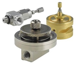
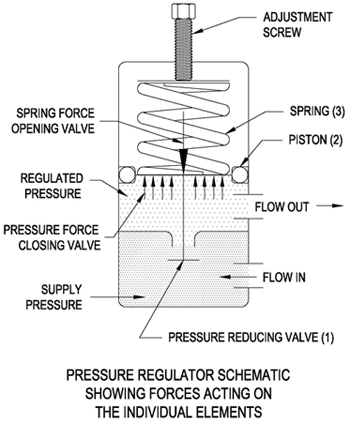
A pressure regulator is comprised of three functional elements: a pressure reducing or restrictive element (generally a poppet valve), a sensing element (generally a diaphragm or piston), and a reference force element (generally a spring). In operation, the spring produces a force that opens the valve. Pressure introduced into the inlet port flows through the valve and then presses against the sensing device (diaphragm or piston). The regulated pressure acts on the sensing element to produce a force that opposes the spring force and closes the valve (see below).
Sensing element (diaphragm or piston)
The most common sensing devices are pistons and diaphragms. Piston-style regulators are often used when higher outlet pressures are required or when outlet pressures are not held to a tight tolerance. For increased accuracy and low-pressure applications, a diaphragm-style design is preferred.
Regulator accuracy and capacity
The accuracy of a regulator is typically defined by charting a given outlet pressure versus flow rate. The resulting chart shows a reduction in the outlet pressure as the flow rate increases. This is a phenomenon known as droop. Pressure regulator accuracy and capacity are defined by the amount of droop for a given range of flows. The performance curve for a given pressure regulator should be carefully examined to ensure the regulator meets the needed performance requirements.
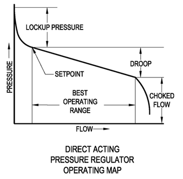
Droop definition
Droop is a term used when the outlet pressures drops below the set point as flow increases. The above "droop" curve is important to a user, because it shows the useful regulating capacity of a regulator. Droop is also caused by inlet pressure variations. As inlet pressures rise, outlet pressure falls. Conversely, as inlet pressures fall, outlet pressures rise.
Orifice size
Increasing the valve port size can increase flow capacity; however, a valve that is oversized makes the regulator sensitive to fluctuating inlet pressures (excessive droop/rise).
Single-stage regulator
Single-stage regulators are an excellent choice for relatively small reductions in pressure. For example, the air compressors used in most factories generate maximum pressures in the 100- to 150-psi range. This pressure is piped through the factory but is often reduced with a single-stage regulator to lower pressures (10 psi, 50 psi, 80 psi, etc.) to operate automated machinery, test stands, machine tools, leak test equipment, linear actuators, and other devices. Single-stage pressure regulators typically do not perform well with large swings in inlet pressure and/or flow rates.
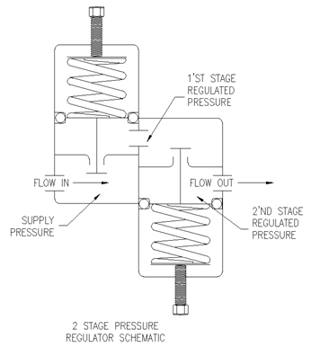
Dual-stage regulator
In cases where the flow rate has large variations or inlet pressures are fluctuating or decaying over time (like with gas tanks/storage cylinders), a two-stage pressure regulator is ideal. These regulators are often used in GC instrumentation, semiconductor applications, and hydrogen fuel cells.
With most single-stage regulators, a large drop in inlet pressure will cause a slight increase in outlet pressure. In a two-stage design, the second stage will not see these large changes in the inlet pressure (only the very slight fluctuations from the outlet of the first stage). This will keep the outlet pressure of the second stage much more stable.
In applications using tanks of gases as often is used in fuel cell applications, a two-stage or three-stage regulator is ideal. A two-stage pressure regulator will compensate for the drop in inlet pressure as the gas is depleted without affecting the outlet pressures in the second stage.
Now that you have chosen the regulator that best suits your application, it is time for installation. A filter installed upstream of the regulator will ensure the valve seat is not contaminated or damaged by particulates. Gases should be free of excessive moisture to prevent icing of the regulator at high flow rates. Gases should also be free of any oils, greases, or other contaminants that may foul or damage the valve components.
If the pressure regulator will be used with oxygen, be aware that this fluid requires specialized knowledge for safe system design, and oxygen-compatible lubricants must be specified. Do not connect regulators to a supply pressure source that has a maximum pressure greater than the rated inlet pressure of the regulator. A pressure regulator is not intended to be used as a shutoff device. When the regulator is not in use, the supply pressure should be turned off.
Installation
- Begin by connecting the pressure source to the inlet port and the regulated pressure line to the outlet port. If the ports are not marked, make sure you double-check with the manufacture to avoid possible damage to the internal components if connected incorrectly.
- Before turning on the supply pressure to the regulator, back off the adjustment control knob to ensure that flow is not being introduced through the regulator. The supply pressure can now be turned on gradually so as not to "shock" the regulator with a sudden rush of pressure.
- Set the pressure regulator to the desired outlet pressure.
If the regulator is of the non-relieving type, it will be easier to adjust the outlet pressure if the regulator is flowing and not "dead-ended." If the pressure exceeds the desired outlet pressure, vent the fluid from the downstream side of the regulator. Never vent fluids by loosening fittings, as injury may result.
On a relieving-style regulator, counterclockwise rotation of the adjustment screw/knob/cap(s) will vent fluid from the downstream side of the regulator and lower the outlet pressure. Do not use relieving-style regulators with flammable or hazardous fluids. Be sure the excess fluid is vented safely and in accordance with all local/state/federal regulations.
- To obtain the desired outlet pressure, make the final adjustments by slowly increasing the pressure from below the desired set point. If the set point is overshot while setting the pressure regulator, back off the set pressure to a point below the set point and gradually increase the pressure back up to the desired set point.
- Cycle the supply pressure on and off several times while monitoring the outlet pressure to be sure the regulator is returning to the pressure set point reliably. The outlet pressure should also be cycled on and off to ensure the pressure regulator is returning to the set point.
- Take care during operation not to turn in the adjustment screws/knobs/cap(s) so far that the reference spring(s) reach solid height and thus eliminate any pressure regulation.
You can find Beswick's available pressure regulators in Beswick's online catalog: Click here for pressure regulators.
Source: Beswick Engineering
Published September 2013
Rate this article
View our terms of use and privacy policy